

Electrical Blueprint Reading Revised eBook (PDF)
Shows how to read and interpret electrical drawings, wiring diagrams, and specifications for constructing electrical systems. Shows how a typical lighting and power layout would appear on a plan, and explains what to do to execute the plan. Describes how to use a panelboard or heating schedule, and includes typical electrical specifications.
This e-Book is the download version of the book in text searchable, PDF format. Craftsman eBooks are for use in the freely distributed Adobe Reader and are compatible with Reader 5.0 or above. Get Adobe Reader.
| Weight | 0.000000 |
|---|---|
| ISBN | 0-934041-64-4 |
| Page Count | 208 |
| Author | Taylor F. Winslow - Revisions and new illustrations by E. Glenn Engineering |
| Publisher | Craftsman Book Company |
Electrical Blueprint Reading, Revised by Taylor F. Winslow Revisions and new illustrations by E. Glenn Engineering
- Contents
- Chapter
1
-
Electrical Drawing, 7
- Types of Electrical Drawings, 7 - Electrical Working Drawings, 11
- Chapter
2
-
Layout of Electrical Drawings,
16
- Preparing Drawings, 16 - Architect's Scale, 17
- Chapter
3
-
Electrical Symbols, 23
- Lighting Outlets, 23 - Switches and Receptacles, 25 -
- Service Equipment, Feeders, and Branch Circuits, 26 -
- Communication and Alarm Symbols, 26
- Lighting Outlets, 23 - Switches and Receptacles, 25 -
- Chapter
42
-
Types of Building Drawings, 28
- Lighting Fixtures, 29 - Lighting Circuits, 30
- Chapter
5
-
Sectional Views and Electrical
Details, 38
- Sectioning, 38 - Electrical Details, 42
- Chapter
6
-
Electrical Wiring Diagrams, 50
- Single-line Diagrams, 51 - Riser Diagrams, 52
- Chapter
7
-
Electrical Schedules, 61
- Connected-Load Schedule, 62 - Panelboard Schedules, 63 -
- Electric-Heat Schedule, 64 - Kitchen-Equipment Schedule, 64 -
- Schedule of Receptacle Types, 69
- Connected-Load Schedule, 62 - Panelboard Schedules, 63 -
- Chapter
8
-
Site Plans, 70
- Civil Engineer's Scale, 70 - Developing Site Plans, 71 -
- Practical Applications, 71 - Underground Distribution, 76
- Civil Engineer's Scale, 70 - Developing Site Plans, 71 -
- Chapter
9
- Electrical Specifications, 82
- Chapter
10
-
Reproductions of Drawings, 111
- Blueprinting, 111 - Blueline or Whiteprinting, 111 -
- Photocopying, 111 - Microfilming, 112
- Blueprinting, 111 - Blueline or Whiteprinting, 111 -
- Chapter
11
-
Equipment and Appliance Wiring,
114
- Carrying Capacity of Conductors, 114 -
- Reading Equipment Blueprints, 129 -
- Color Codes, 131 - Schematics for International Wiring, 133
- Carrying Capacity of Conductors, 114 -
- Appendix
A
- Practice Test, 146
- Appendix
B
- Final Exam, 152
- Appendix
C
- Answers to Assignments and Tests, 155
- Appendix
D
- Symbols and Abbreviations, 163
- Appendix
E
- Sample Forms, 184
- Appendix
F
- Glossary, 194
- Index,
202
Electrical Blueprint
Reading
Revised
by Taylor F. Winslow
Revisions and new illustrations by
E. Glenn Engineering
Chapter One
ELECTRICAL DRAWINGS
An electrical blueprint is an exact copy or reproduction of an original drawing, consisting of lines, symbols, dimensions, and notations to accurately convey an engineer's design to workmen who install the electrical system on the job. The student should keep in mind that the workmen must be able to take a blueprint, and without further instructions, install or produce the electrical system as the engineer or draftsman intended it to be accomplished. A blueprint, therefore, is an abbreviated language for conveying a large amount of exact, detailed information, which would otherwise take many pages of manuscript or hours of verbal instruction to convey.
In every branch of electrical work, there is often occasion to read an electrical drawing. Electricians, for ex- ample, who are responsible for installing the electrical system in a new building, usually consult an electrical drawing to locate the various outlets, the routing of circuits, the location and size of panelboards, and other similar electrical details, in preparing a bid. The electrical estimator of a contracting firm must refer to electrical drawings in order to determine the quantity of material needed. Electricians in industrial plants consult schematic diagrams when wiring electrical controls for machinery. Plant maintenance men use electrical blueprints in troubleshooting. Circuits may be tested and checked against the original drawings to help locate any faulty points in the installation.
TYPES OF ELECTRICAL DRAWINGS
Electrical Construction Drawings
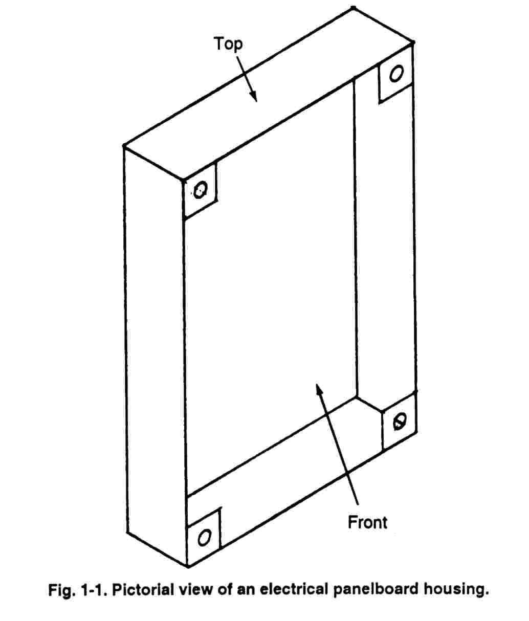
Drawings that represent the physical arrangement and views of specific electrical equipment are called electrical construction drawings. These drawings give all the plan views, elevation views, and other details necessary to construct the job. Fig. 1-1 shows a sketch of an electrical panelboard "can," or housing. One side of the housing is labeled "front" and another side, "top".
 In
Fig. 1-2, the drawing labeled "top" is what you see when you look
directly down at the top of the housing, and in doing so, the sides, the bottom,
the front, and the back are cut from your view.
In
Fig. 1-2, the drawing labeled "top" is what you see when you look
directly down at the top of the housing, and in doing so, the sides, the bottom,
the front, and the back are cut from your view.
The drawing labeled "front" is what you see when the block is directly in front of you. In this case, you cannot see the top, bottom, back, or the two sides.
A "side" view is what would be seen if the right side of the housing was turned toward you. This cuts from your view the top, the bottom, the front, the back, and the left sides.
The width of the housing is shown by the horizontal lines of the top view and the horizontal lines of the front view. The height is shown by the vertical lines of both the front and the side views, and the depth is shown by the vertical lines of the top view and the horizontal lines of the side view.
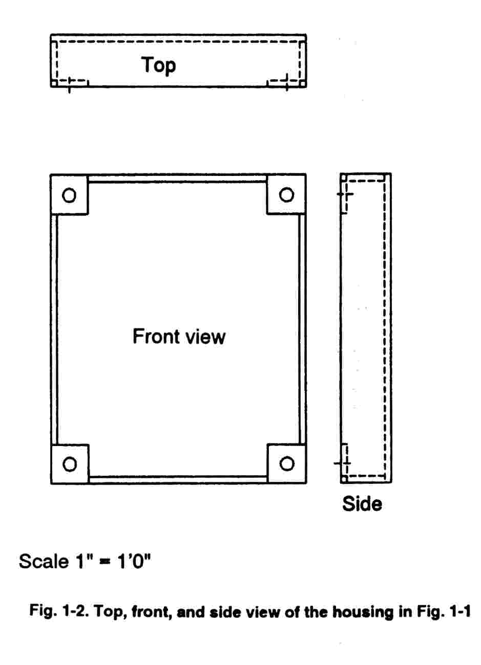 These
three drawings-the top, front, and side views-tell all about the shape of the
housing, but they do not indicate the size of the housing. There are two common
methods to indicate the actual length, width, and height of the housing. One is
to draw these views to some given scale, such as 1" = 1'-0". This
means that 1 inch on the drawing represents 1 foot in the actual construction of
the housing. The second method is to give dimensions on the drawings; this
method can be seen in Fig. 1-3. Note that the gauge and type of material are
also given in this drawing. The drawing is also drawn to scale.
These
three drawings-the top, front, and side views-tell all about the shape of the
housing, but they do not indicate the size of the housing. There are two common
methods to indicate the actual length, width, and height of the housing. One is
to draw these views to some given scale, such as 1" = 1'-0". This
means that 1 inch on the drawing represents 1 foot in the actual construction of
the housing. The second method is to give dimensions on the drawings; this
method can be seen in Fig. 1-3. Note that the gauge and type of material are
also given in this drawing. The drawing is also drawn to scale.
The
drawings of the panelboard housing that was just covered are typical of an
electrical construction drawing. They indicate how the equipment will look when
completed and show more clearly than any other electrical drawing the actual
outlines of equipment installed in their respective locations. All details of
the equipment and materials to be used are given on these drawings, and all
dimensions, notes, and references are shown. The complete construction drawing
gives all the physical information necessary for installing or erecting the
equipment.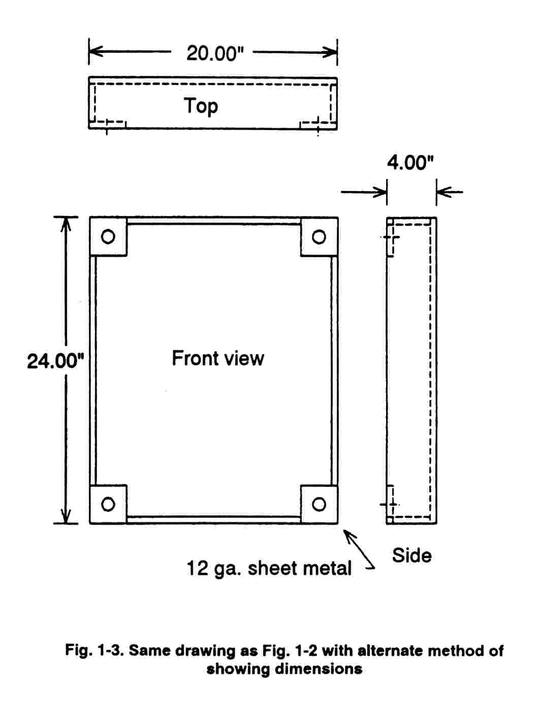
Electrical construction drawings, such as the drawing of the panelboard housing in Fig. 1-3, are used by electrical-equipment manufacturers. Electric utility companies also use drawings, such as the one in Fig. 1-4 giving details on the construction of a high-voltage trans- mission line. A consulting engineering firm may use an electrical construction drawing to supplement building electrical-system drawings for a special installation (Fig. 1-5). The latter is often referred to as an electrical detail drawing.
Electrical Diagrams
Electrical
diagrams are drawings that are intended to show, in diagrammatic form,
electrical components and their related connections. They are seldom, if
ever, drawn to scale, and show only the electrical association of the different
components. In diagram drawings, symbols are used extensively to represent the
various pieces of electrical equipment, and lines are used to connect these
symbols, indicating the size, type, and number of conductors (wires) that are
necessary to complete the electrical circuit.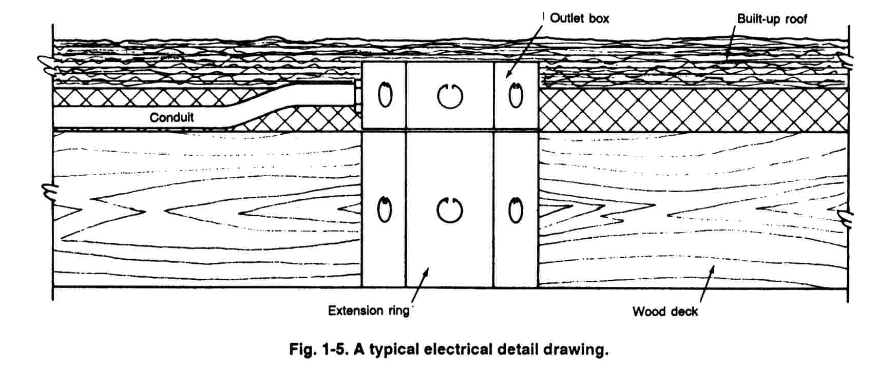
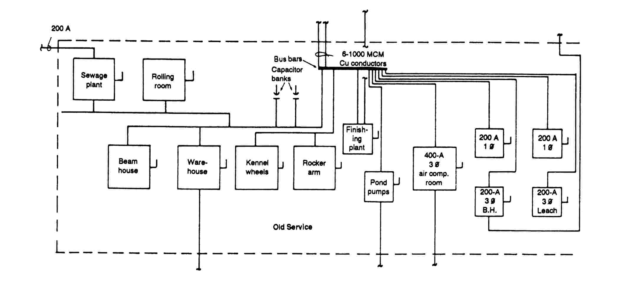
Single-line block diagrams are used extensively by consulting engineering firms to indicate the electric service equipment. The power-riser diagram in Fig. 1-6, for example, is typical of such drawings. The drawing shows all pieces of electrical equipment as well as the connecting lines used to indicate the circuits. Notes are used to identify the equipment, indicate the size of conduit necessary for each circuit, and the number, size, and type of conductors in each conduit. A panelboard schedule usually is included with single-line power-riser diagrams to indicate the exact components (fuses, circuit breakers, etc.) contained in each panelboard.
 A
schematic wiring diagram (Fig. 1-7) is similar to a single-line block diagram
except that the schematic diagram gives more-detailed information and the actual
number of wires used for the electrical connections are shown.
A
schematic wiring diagram (Fig. 1-7) is similar to a single-line block diagram
except that the schematic diagram gives more-detailed information and the actual
number of wires used for the electrical connections are shown.
ELECTRICAL WORKING DRAWINGS
Electrical working drawings that are prepared by architects and consulting engineers to describe the electrical system in a building are very unique drawings. Most drawings encompass all of the previously described types of electrical drawings on each separate building project. For example, a complete set of working drawings for an electrical system usually will consist of the following:
- A plot plan showing the location of the building on the property and all outside electrical wiring, including the service entrance. This plan is drawn to scale with the exception of various electrical symbols which must be enlarged to be readable. Fig. 1-8 shows a typical building plot plan with related electrical wiring.
- Floor plans showing the walls and partitions for each floor or level. The physical location of all wiring and outlets are shown for lighting, power, signal and communication, special electrical systems, and related electrical equipment. Again, the building partitions are drawn to scale as are such electrical items as fluorescent lighting fixtures, panelboards, and switchgear. The locations of other electrical outlets and similar components are only approximated on the drawings because they have to be exaggerated. To illustrate, a common duplex receptacle is only about three inches wide. If such a receptacle were to be located on the floor plan of a building that was drawn to a scale of 1/8" = 1'-0", a small dot on the drawings would be too large to draw the receptacle exactly to scale. Therefore, the symbol is used to indicate a duplex receptacle and is clearly shown. When the electrician on the job is locating these outlets, he usually measures to the center of the circle to determine the distance between the outlets (Fig. 1-9).
- Power-riser diagrams to show the service-entrance and panelboard components (Fig. 1-10).
- Control wiring schematic diagrams (Fig. 1-11).
- Schedules, notes, and large-scale details on construction drawings (Fig. 1-12).
In order to be able to "read" an electrical drawing, one must become familiar with the meaning of symbols, lines, and abbreviations used on the drawings and learn how to interpret the message conveyed by the drawings.
SUMMARY
A blueprint or an electrical drawing is an abbreviated language for conveying a large amount of exact, detailed information, which would otherwise take many pages of manuscript or hours of verbal instruction to convey.
Types of electrical drawings usually fall into the following categories:
- Electrical construction drawings.
- Single-line block diagrams.
- Schematic wiring diagrams.
Electrical working drawings for building construction normally utilize all of the previously described types of electrical drawings.
An electrical working drawing for building construction usually will consist of: a plot plan, floor plans, sectional drawings, various details, wiring diagrams, and schedules.
![]() Electrical
Blueprint Reading, Revised
Electrical
Blueprint Reading, Revised
by Taylor F. Winslow
Revisions and new illustrations by E. Glenn Engineering
Whether you're studying to be an electrician, or a seasoned professional looking to improve your blueprint-reading skills, this newly-revised manual will help you stay competitive in today's electrical job market. It shows you how to read and interpret all types of electrical drawings and diagrams used in residential and commercial construction. There are details on electrical floor plans, lighting layouts, and schematics showing single line and block or power-riser diagrams for wiring circuits. You'll learn how to lay out an electrical project, what to look out for in dealing with construction specifications and drawings especially in terms of today's technology, how to use an engineer's scale for developing and reading site plans, and how to make up and use panelboard, connected-load, and other schedules.
This new edition provides:
- Dozens of drawings, diagrams, and blueprint reproductions, recently redrawn and updated
- Sample electrical specifications and forms
- Sample problems and a Final Exam (answers included)
- A glossary of terms and a guide to electrical symbols
Reading a blueprint is like reading a road map. It tells you exactly what you're required to build. Read it wrong and you'll build it wrong - and that can be expensive. This book will teach you how to get the information you need from the most complex electrical blueprints. Once you understand how to follow the pathways and interpret the scale and symbols, you can install the correct system the way the designer intended. Keep this book as a handy reference. Once you've learned the techniques it explains, you'll no longer face the bewilderment and frustration of having to build from electrical blueprints you can't read.